

Having to manually drive the rotor has become a pain as I have to keep an eye on the rotor controller while also occupying a hand to drive the controller. I am a fan of Yaesu rotors and while models are offered with external interfaces, I chose poorly many years ago and selected a model without an external interface.
Researching the problem I had three options.
- Upgrade the rotor to a model with a computer interface
- Replace the controller with a third party solution such as the Hy-Gain YRC-1.
- Add remote control to my existing controller.
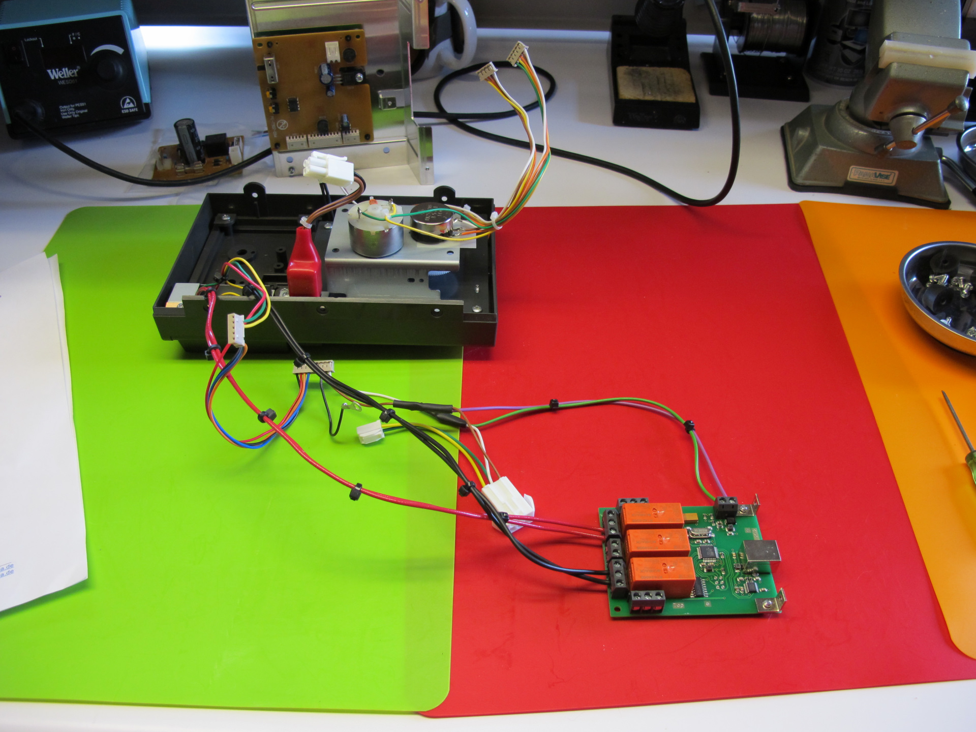
I chose option 3 and ordered a pre-built ERC Ver 4 SMD USB from Vibroplex.
The controller arrives with documentation, a CD with software, install guides and other materials. Also in the box is mounting hardware and wire to connect the interface to your rotor controller.
After I had already torn into the Yaesu controller I realized this would be a good blog article. Apologies for not having step by step disassembly pics. You should be able to figure it out.
Step 1 Card Placement
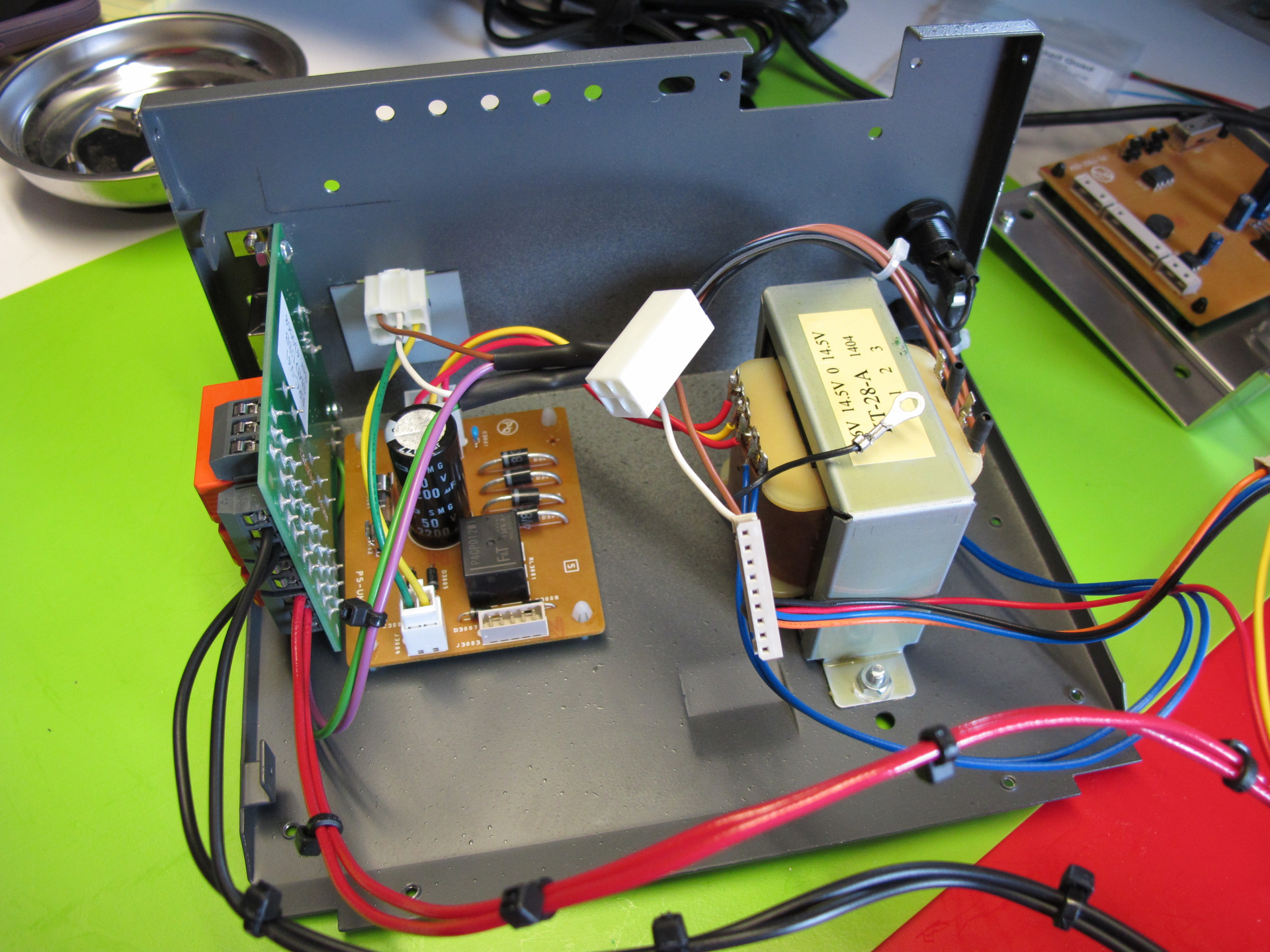
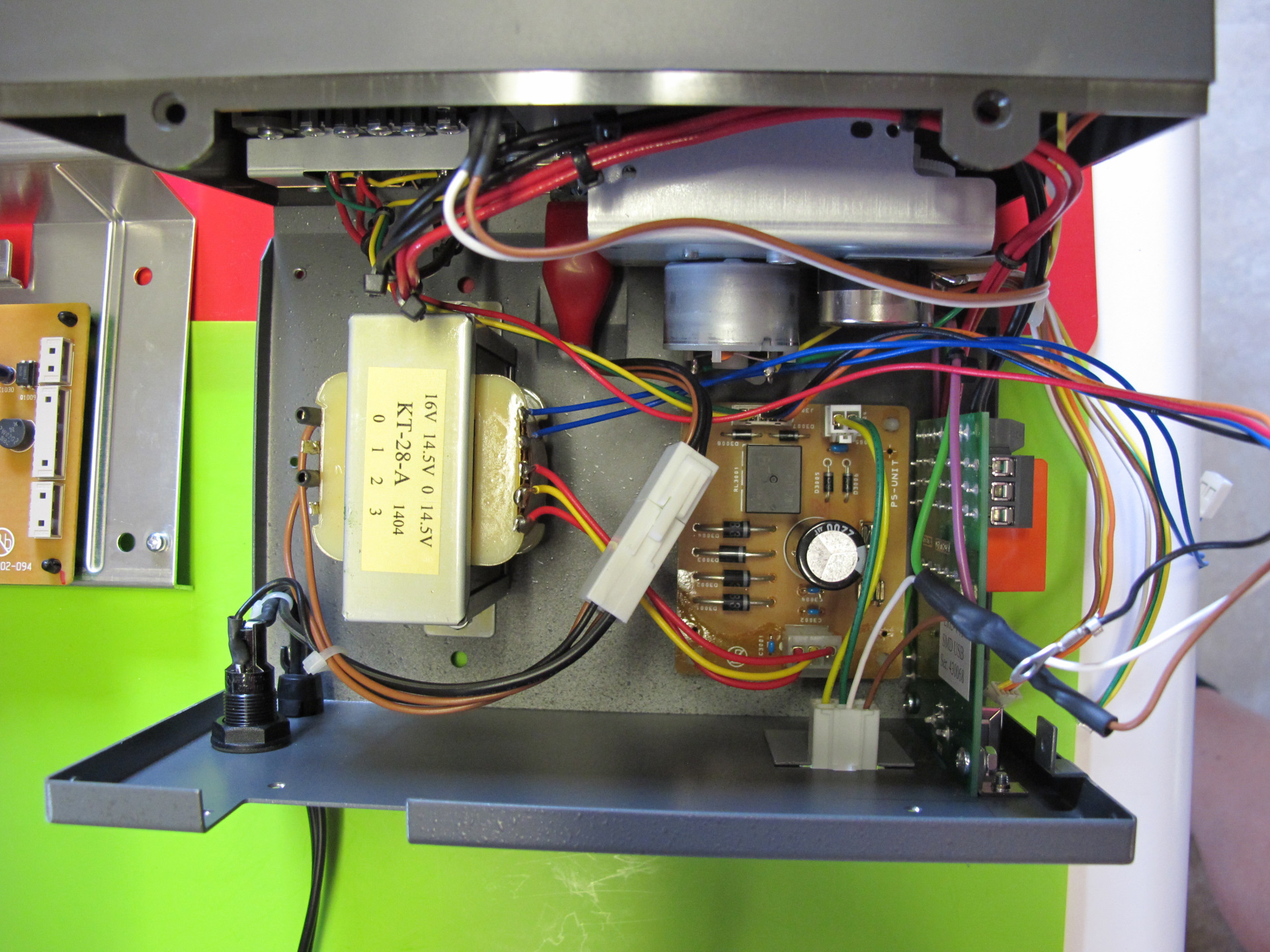
Take the Yaesu controller apart

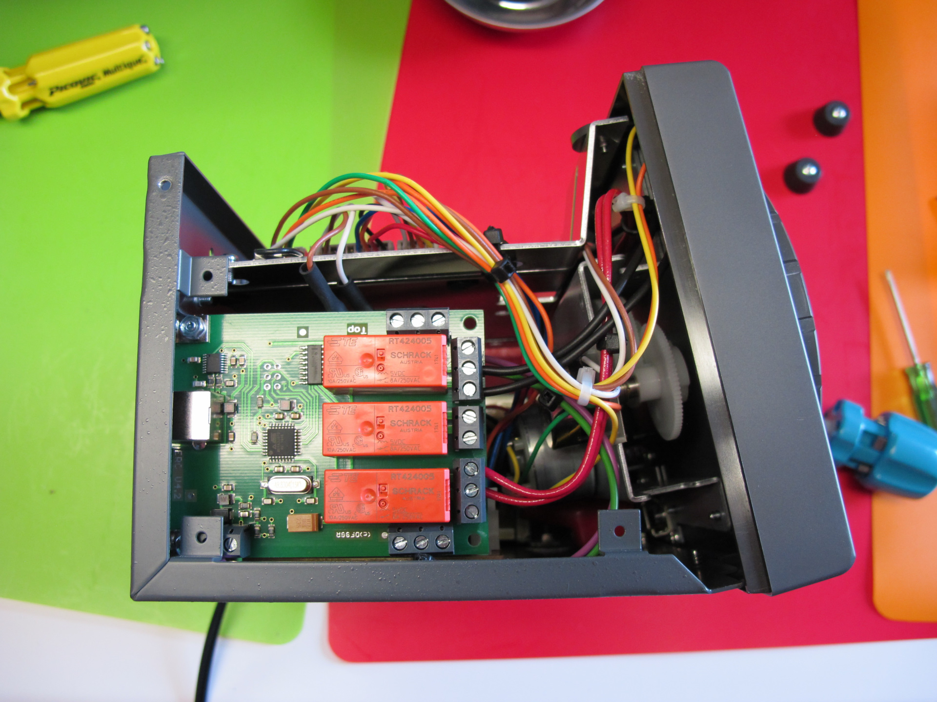
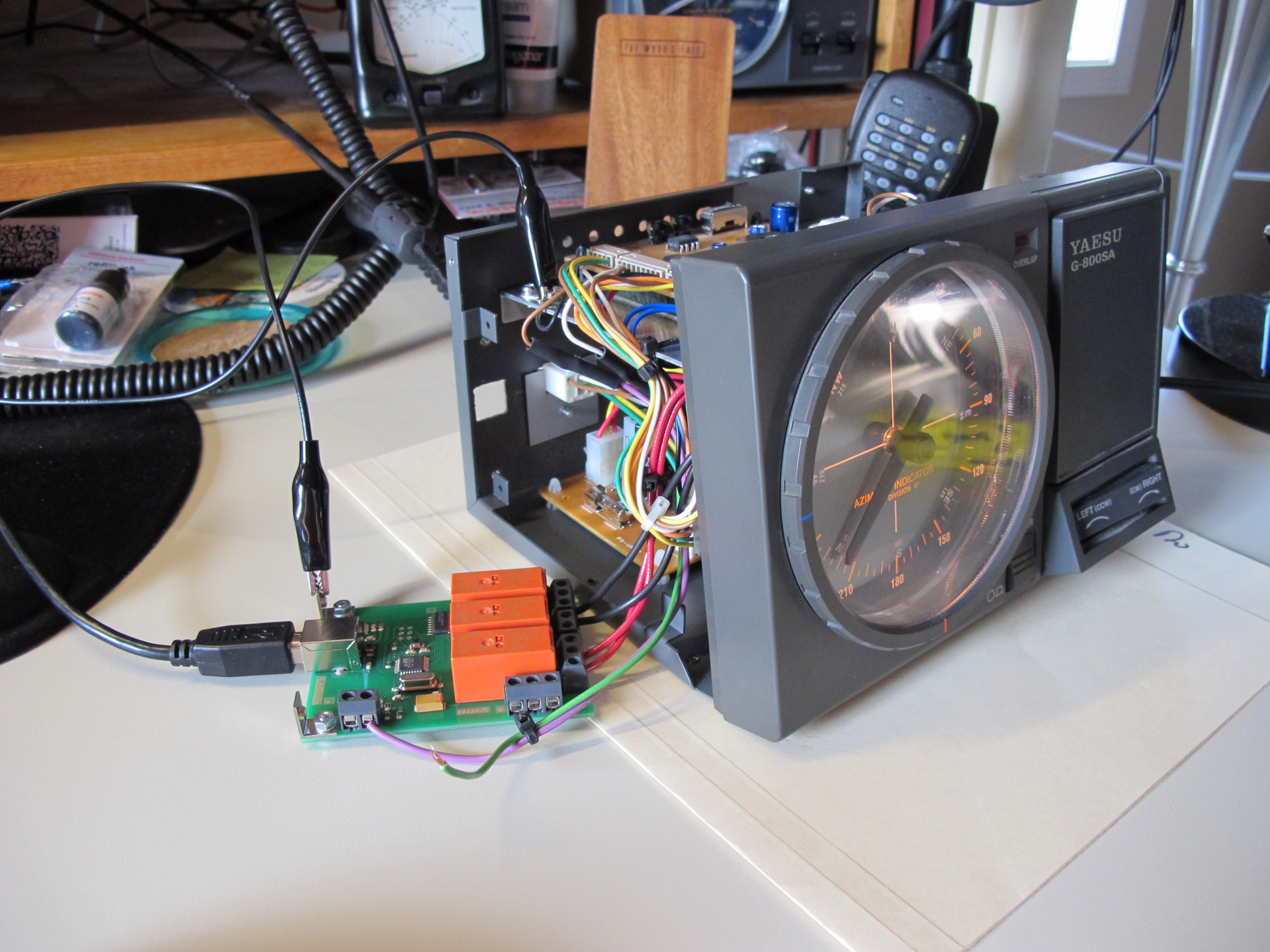
It is rather tight inside I chose to place the controller vertical on the left side near the rotor cable connector. I outlined the other components and brackets in the area to aid in placement.
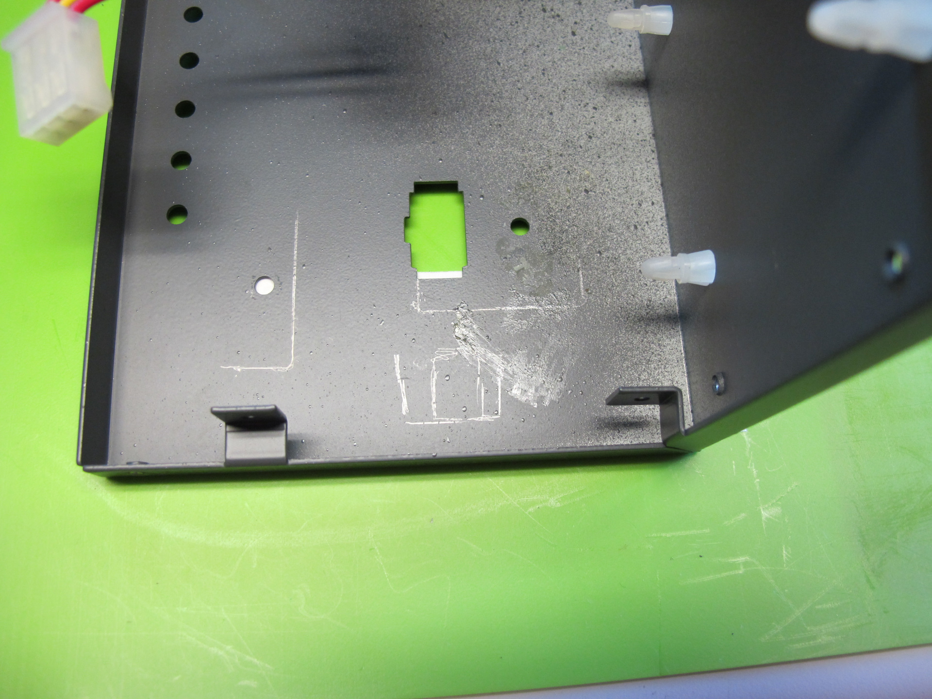
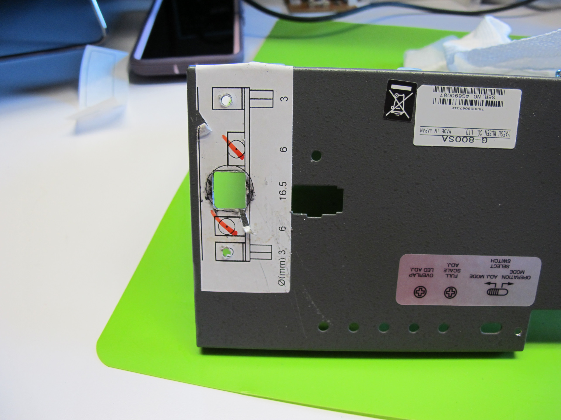
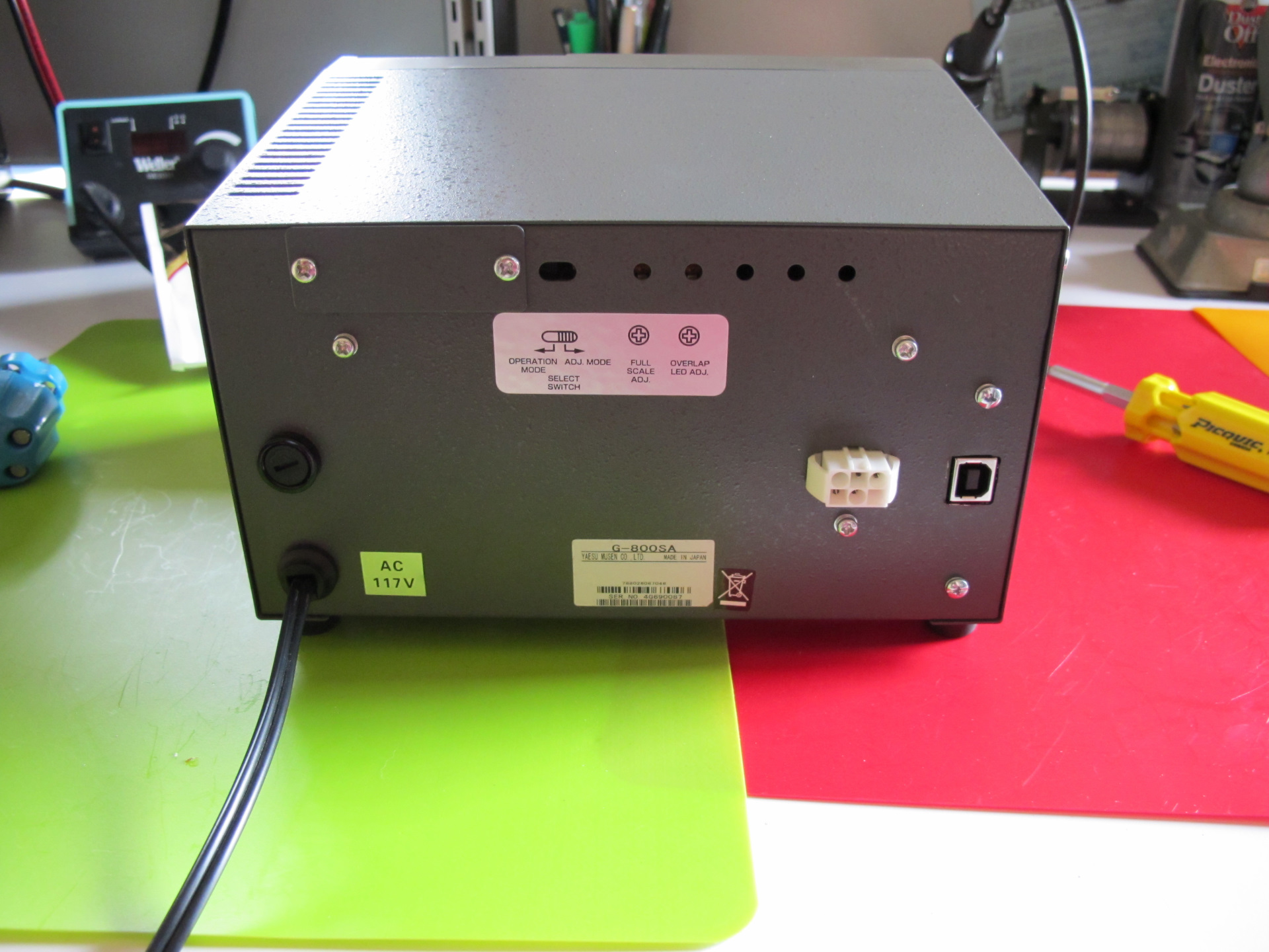
With the internal location placed, I used a sticker provided in the kit to layout the locations on the outside of the case.
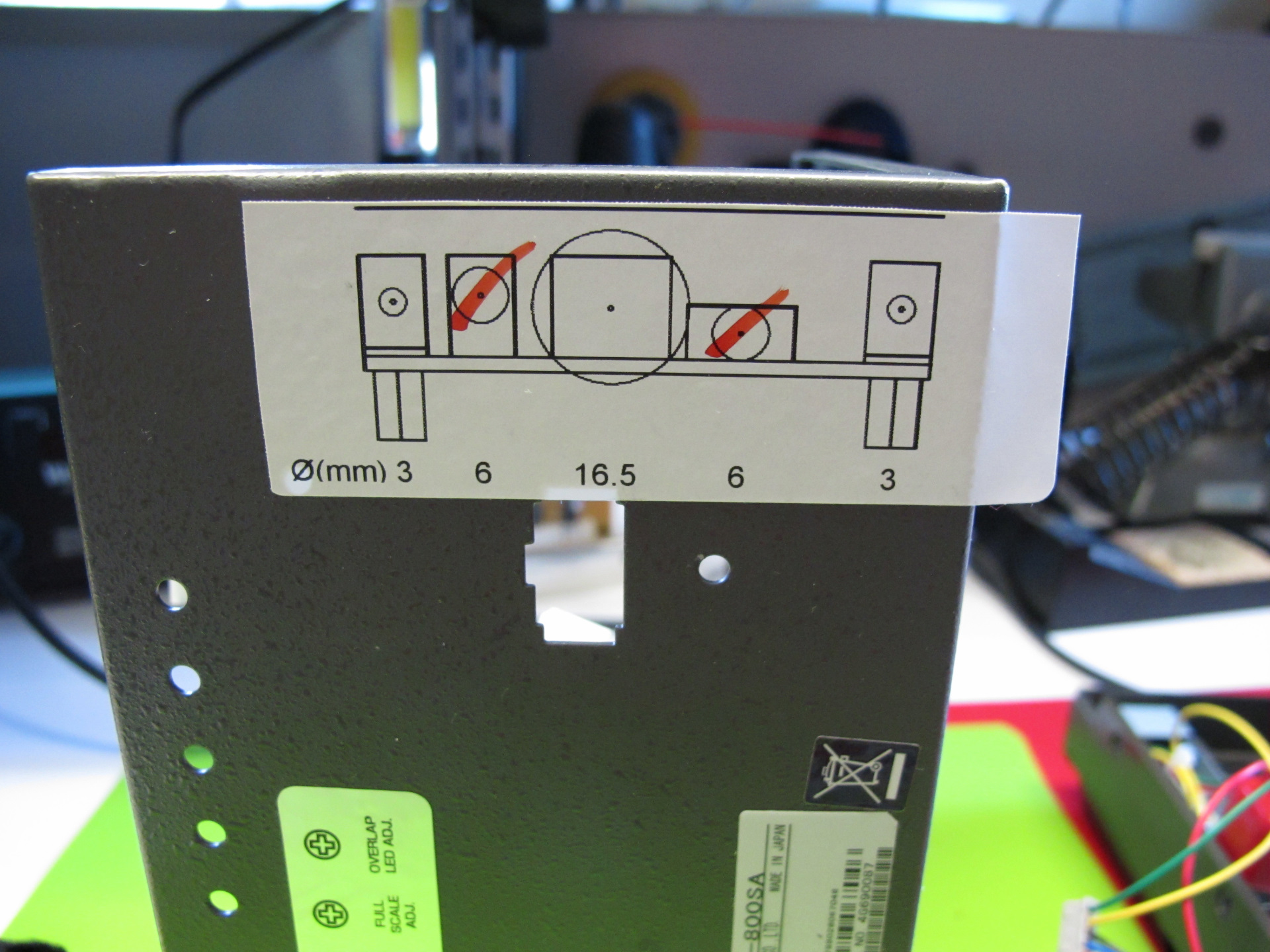
30 minutes later the drilling, nibbling and filing is done.
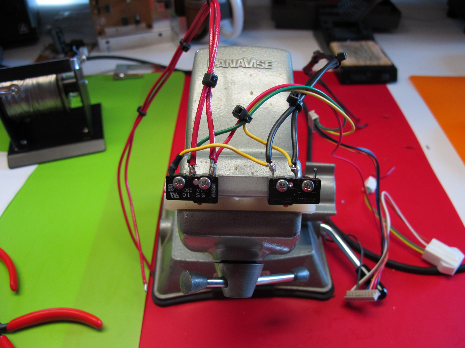
Step 2 Wire up the interface points
The controller interconnect is simple with the G-800SA, relays on the ERC mimic the manual micro switches and a parallel connection is made to the variable resistor heading circuit in the rotor.
The connection to the rotors sense circuit would I discover during calibration cause issues. More on this in the calibration section.
Taping into the position circuit is all the remains
Step 3 – Reassembly
Step 4 – Calibration
On power up I discovered a problem which I have not yet opened a support ticket on. The ERC places a voltage divider circuit in parallel across the rotors position potentiometer to sense po. Well this is a problem for the Yaesu position circuit. This parallel resistance significantly screws up the accuracy of the Yaesu indicator. The front panel controls still work of course however the position indicated can be off by 30 or more degrees. This was confirmed by disconnecting the sense circuit all returned to normal.
On the positive side once the EBC is calibrated visually with the antenna position it is fairly accurate and can be used. I will just need to ignore the controller indicator.
Operation
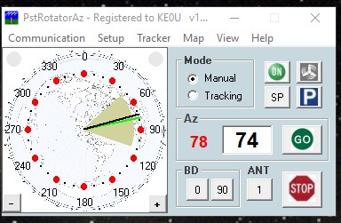
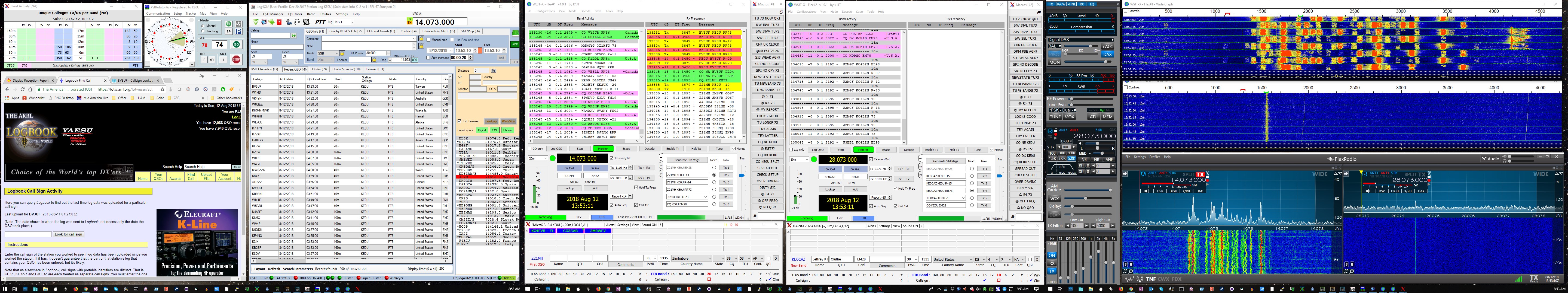
Once I determined that the position presented by the ERC was fairly accurate I was able to integrate into station operations. Using the wonderful PstRotator Az application. The app can drive the EBR controller and talk with my radio (Flex 6500) and logger (Log4OM).
It sure is nice to just click on a heading or click on the rotor icon in Log4om and let the ERC do the rest.
Until next time.
73, Jay
Have you tried to increase the resistance of the voltage divider? As long as the ratio is kept the same, you can increase the overall resistance, reducing the load on the indicator. The only drawback to this is the signal from the voltage divider to the ERC microcontroller is more susceptible to noise.
Another option would be to create a buffer circuit using an opamp. You could either create a unity gain amp to feed the ERC voltage divider or implement the appropriate voltage scaling in the opamp circuit and do away with the voltage divider. Since the input to the opamp is high impedance, it should not influence the meter display. This is the same way you can measure something with a multimeter without influencing the circuit very much.
Reid,
Thanks for sharing your thoughts on the problem.
Jay
Hi Jay. Thanks for this write up. I too have a G800sa and am installing the ERC4 USB. This web page is very helpful. I am impressed that you have sussed out the poor wiring diagram provided with this kit or did you find a more comprehensive direction for wiring and mounting the board, somewhere else. No where in the supplied instructions does it say what pins to use on the ERC board. Not in the docs I was supplied with anyway. I have gone through all the .pdf files on the cd to no avail so I am grateful to find this page and your wonderful photos of your progress. Many Thanks de VE3XKZ
Chris,
I enjoyed the build good to hear my doc helped you out, sadly I was never able to get the front dial to be accurate. I no longer use that particular controller took a direct tower hit that smoked the controller. The rotor fortunately was not zapped.
73, Jay
Thats too bad Jay. Strange about the dial. What controller are you using now?
73 Chris
The meter is in a voltage bridge if I recall and the additional load of the ERC4 made the circuit non linear. As I was unable to test the rotor and the 800SA is no longer available for purchase I went with a G-800DXA which has an interface built in. So I have a spare rotor and will be on the lookout for Yaesu or third party controller.
I was wondering if the pointing accuracy has since been fixed by Vibroplex. And I was wondering if you had to buy mounting ears for your board. I don’t think I can get those locally. Anyway, I’m considering buying the RS232 version but I might mount it in an external project box rather than cram it inside of the controller. 73 de N0SQ
The metal tabs were included, sadly the rotor was taken out by direct lightning hit.