

Introduction
I received an Arduino Nano as a gift and I was looking for ways to put it to use around the Ham shack. I find that I tend to space out at times and forget to ID. I have tried various PC apps to remind me with little affect. I run a multi monitor and multiple virtual desktop setup and kept loosing the app in all the other apps.
Rather than use a simple kitchen or egg timer I desired a system which was autonomous and would alert me at the zero’s after the hour (10,20,30,40 etc). In order to make it autonomous I had a couple of choices to keep the internal clock in sync, add an Ethernet shield and use NTP or add a GPS shield. In my particular setup I know that an indoor GPS receiver will easily achieve lock so I went this route. If your situation does not permit the use of GPS perhaps a wired or wireless Ethernet solution would work for you.
Initially I used a two line LCD display but changed to the real-time clock (RTC) shield as it is easier to see, has LED’s and buttons, and an internal clock with battery backup which I wish to make use of.
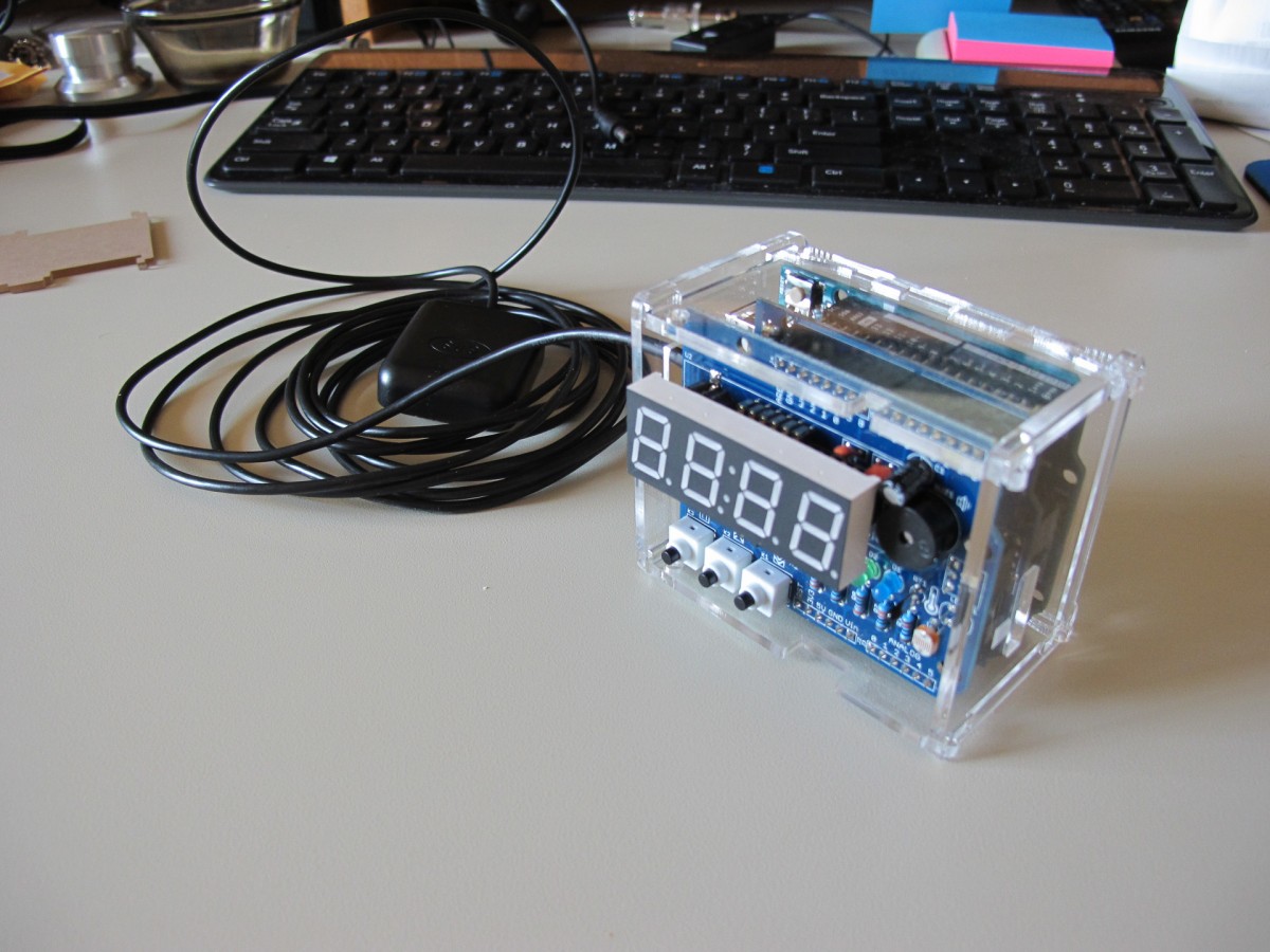
As shown in the pic below the solution consists of an Arduino Nano and two shields. One of the issues with double shields is I/O port conflict. To work around this the GPS uses the same serial pins as the USB port. The downside of this is in order to upload code to the Nano, the RTC shield must be removed and the TX pin jumper removed.

The application
The source (sketch) is attached as is a zip of modified sources for the TickTockShield library. The code is fairly straightforward to read and modify to your personal likes.It however is not perfect, you will see leftover code from experiments and or features I chose not to implement in this revision.
The buttons and buzzer are not currently used and the LED’s are used to indicate various states and actions. The left most LED is D4 and the right most is D1 which is not very intuitive.
D4 = Flashed every other second during the ID minute
D3 = Indicates when the on board realtime clock is out time with the GPS and is being set.
D2 = GPS Lock (less than 4 sats)
D1 = GPS Lock ( 4 or more sats)
The hardest part of this project was tracking down spec sheets and schematics on the shields used in the project. Several of the shields I have bought online for this project and others did not arrive with documentation. But hey if it was easy it would not have been as fun tracking down and experimenting with different approaches.
If you chose to go another direction a quick web search will locate the un-altered libraries and sample source from which you can develop.
Operation
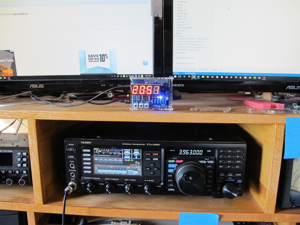
Operation is simple, place the antenna and power it up. Depending on multiple factors the GPS will take sometime to lock at which time the realtime chip on the RTC shield will be set to the current GMT. If you want to observe power up in greater detail un-comment the DEBUG define when uploading code to the Uno. And use the IDE serial monitor to code operation.
The contrast in the pic below is not representative of actual operation the display is very easy to see. And the little LED’s really put out the light and catch your eye at ID time.
Source files
The source and libs I have modified are available for download here. There may be libs needed outside of what I have provided that are easily available on the net.
73’s Until next time
Jay
Leave a Reply